What happens during production impact testing? What are the latest ASME code updates? How are lethal chemicals transferred? These are just a few of the questions you'll find answers to in our fabrication blog. Browse and share these articles, and as always, let us know how we can help.

What ASME Code Stamps Really Tell You About Your Fabricator
March 30, 2026 When you’re sourcing pressure vessels or boilers for an industrial project, ASME Code Stamps aren’t just a formality; they’re your assurance of safety, regulatory compliance, and build quality. Knowing the difference between the U, R, and S stamps helps you make smarter decisions and avoid costly mistakes. Since 1910, Boardman LLC has helped projects like … Continue reading "What ASME Code Stamps Really Tell You About Your Fabricator" ...Read More
Why is Pressure Vessel Failure the Catastrophic Risk No Facility Can Afford to Ignore?
February 27, 2026 A pressure vessel does not “sort of” fail. It does not give you the courtesy of a gradual breakdown like a worn belt or a tired motor. When a pressure vessel failure happens, it can be sudden, violent, and unforgiving, turning a controlled industrial process into a split-second emergency. The most chilling part is that … Continue reading "Why is Pressure Vessel Failure the Catastrophic Risk No Facility Can Afford to Ignore?" ...Read More
Welding and Fabrication Needs You Can’t Ignore in Turnaround Maintenance for Refineries
December 10, 2025 When a refinery schedules major downtime, it becomes mission-critical to execute swiftly and accurately. A well-executed turnaround maintenance effort can restore performance, extend equipment life, and prevent costly unplanned shutdowns. But when welding and fabrication options aren’t aligned with the refinery’s exact needs, delays and budget overruns become very real risks. In this environment, understanding … Continue reading "Welding and Fabrication Needs You Can’t Ignore in Turnaround Maintenance for Refineries" ...Read More
Emergency Metal Services and Why Certain Industries Can’t Afford a Single Hour of Downtime
November 13, 2025 In high-stakes industrial environments, a cracked weld, a ruptured vessel nozzle, or a damaged conveyor frame is never “just a repair.” It is lost throughput, missed contracts, and cascading safety and compliance risks. And the meter runs fast! Independent surveys peg unplanned downtime at around $125,000 per hour on average across industrial operations, but that … Continue reading "Emergency Metal Services and Why Certain Industries Can’t Afford a Single Hour of Downtime" ...Read More
Quarterly Newsletter: Nozzle Overview
October 13, 2025 ...Read More

Why Is Turnaround Maintenance a Strategic Asset for Chemical and Petrochemical Plants?
October 3, 2025 Chemical and petrochemical plants fuel the global economy, supplying materials for construction, energy, healthcare, and consumer goods. But operating these facilities is challenging—equipment runs under high pressure, harsh conditions, and strict regulations. Unplanned breakdowns are costly and pose serious risks to people, the environment, and production. This is why turnaround maintenance has become a cornerstone … Continue reading "Why Is Turnaround Maintenance a Strategic Asset for Chemical and Petrochemical Plants?" ...Read More
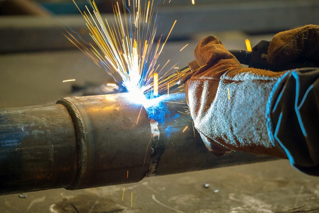
How Are Emergency Welding Services the Backbone of Industrial Uptime?
September 10, 2025 When production grinds to a halt, the ripple effects are immediate and often costly. Emergency welding services aren’t just a convenience in industries where every second of downtime chips away at profitability and safety. They’re a critical lifeline. From energy plants and chemical facilities to manufacturing floors and food processing lines, the need for rapid … Continue reading "How Are Emergency Welding Services the Backbone of Industrial Uptime?" ...Read More
Quarterly Newsletter: Post Weld Heat Treatment (PWHT)
June 27, 2025 ...Read More
Quarterly Newsletter: Design Pressure vs Maximum Allowable Working Pressure vs Maximum Allowable Pressure
April 2, 2025 ...Read More

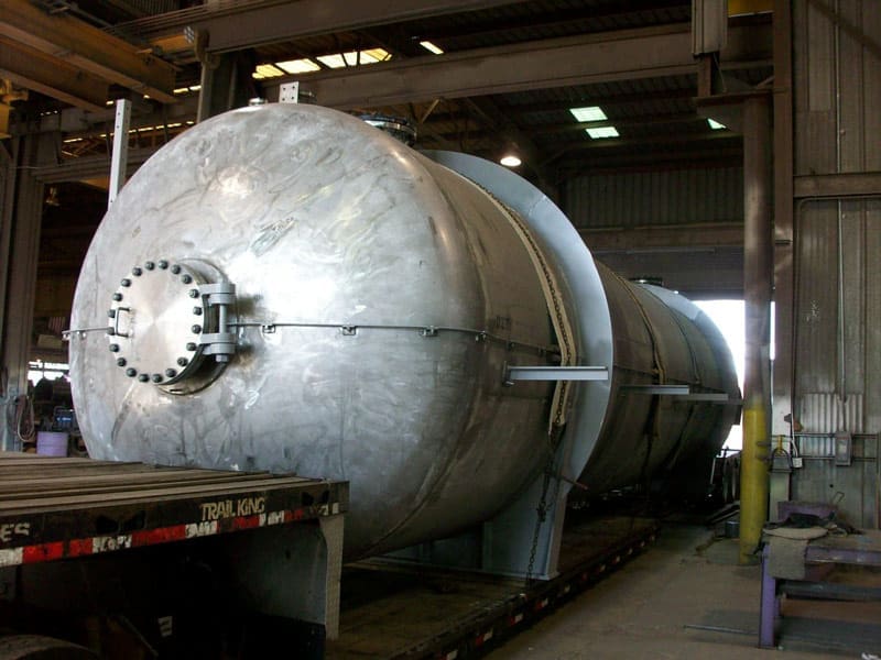
Plate Rolling: What Are Some Essential Techniques for Pressure Vessel Fabrication?
February 24, 2025 Pressure vessel fabrication is a meticulous process that demands precision, skill, and advanced technology. Among the critical steps in this process is plate rolling, an essential technique that shapes the foundation of many pressure vessels. Understanding plate rolling and its role in creating reliable, durable pressure vessels is key for industries relying on these components. … Continue reading "Plate Rolling: What Are Some Essential Techniques for Pressure Vessel Fabrication?" ...Read More